Intelligence BuildoutMethodology

Machine — complete text edition

Volume IV / Text edition

Machine

Nodes + rack systems. 13 spreads and 26 pages, with the complete evidence-linked content. No JavaScript is required.

Volume IV

Machine

Nodes + rack systems · 26 pages

How accelerator packages become serviceable computers through host processors, boards, interconnects, power conversion, firmware, liquid loops, mechanics, and disciplined fleet operations.

01

The heterogeneous node

An accelerator is one component in a managed computer whose boundaries include hosts, memory, links, storage, security, and power.

Spread 01 / From accelerator to node

01 / System assembly

A chip does not arrive as a computer

The deployable unit adds hosts, memory, input/output, power conversion, cooling hardware, management, and a physical service boundary.

An accelerator package can execute specialized operations, but it cannot independently ingest a training corpus, negotiate a network, boot securely, expose health data, or accept facility power. A node surrounds it with host CPUs, system memory, local storage, network interfaces, clocks, voltage regulation, management controllers, and firmware. Boards and chassis route these functions while holding components in precise mechanical and thermal relationships.

This integration layer determines how much packaged silicon becomes schedulable compute. A weak host path can starve accelerators; unreliable firmware can strand healthy hardware; poor airflow or coolant contact can reduce sustained performance. System specifications should therefore separate accelerator attributes from node attributes and rated limits from measured workloads. The useful machine is the combination that can boot, communicate, run, report faults, and be repaired predictably.

The nested machine
LayerPrimary jobTypical failure boundary
PackageCompute and local memoryDie, stack, link, thermal interface
Module / boardPower, routing, attachmentRegulator, connector, signal path
Node / trayHost, management, local I/OFirmware, cooling, component service
RackShared power, fabric, coolant, mechanicsDistribution and maintenance domain
The node inherits four package contracts
Power contract
Steady demand, transient behavior, rail sequence, protection, telemetry, and the conditions that require throttling or shutdown.
Thermal contract
Heat map, allowable temperatures, mounting pressure, interface materials, sensor meaning, and safe response to cooling degradation.
Data contract
Host, memory, scale-up, management, and storage paths together with supported rates, topology, recovery, and software visibility.
A node turns component capability into an operable computer.

Field plate / Installed compute

Integration is visible in the hardware

Cables, rails, manifolds, doors, service clearances, and human access occupy the space omitted by silicon diagrams.

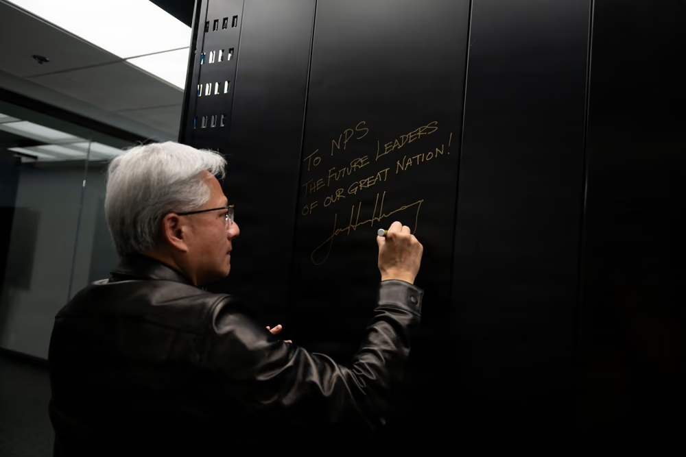
Documentary photographs of installed AI systems show the machine as operators encounter it: first as an enclosure whose doors conceal repeated modules, power and network connections, coolant infrastructure, and constrained working space. Every interface behind that skin carries an operational decision. Cable reach affects replacement; connector orientation affects error risk; aisle access affects repair time; lifting and retention hardware affect worker safety and component damage.

The photographed DGX GB300 cabinet is identified in its media record and provides current physical context for rack-scale compute, even though the closed door leaves its internal service layers out of view. It should not be treated as a universal reference design, a performance benchmark, or proof of broad deployment. What transfers across product generations is the systems lesson: installed compute must coordinate electrical, thermal, mechanical, network, firmware, and service requirements at once.

NVIDIA CEO Jensen Huang writes a dedication on the closed door of a black DGX GB300 system cabinet at the Naval Postgraduate School.

NVIDIA CEO Jensen Huang signs a closed DGX GB300 cabinet at the Naval Postgraduate School; the enclosure is the visible skin around otherwise hidden compute, power, network, cooling, and service layers.

The image documents one identified installation; it does not establish fleet-wide performance, utilization, or adoption.DVIDS marks the item public domain. The cabinet and dedication are documentary context for an identified installation, not an endorsement or a universal rack design. The appearance of U.S. Department of War (DoW) visual information does not imply or constitute DoW endorsement. Individuals' publicity and privacy rights are not waived.U.S. Navy photo by MC2 Abreen Padeken, via DVIDS, public domain.Original sourceU.S. government work / public domain
Define the node failure domain
  • Identify which faults isolate one accelerator, one tray, one scale-up group, or the entire chassis, and which shared components create hidden coupling.
  • Separate serviceable field-replaceable units from factory-only assemblies so availability models use realistic repair boundaries and handling procedures.
  • Document degraded modes: reduced links, reduced memory, throttled power, unavailable peers, or management-only access must have explicit scheduler and safety behavior.
The machine is silicon plus every interface required to keep it useful.

Spread 02 / Node anatomy

02 / Components

Heterogeneous parts divide the work

Accelerators perform parallel mathematics while hosts, network devices, storage, and controllers move and govern the surrounding state.

A typical AI node combines different processor roles. Accelerators handle dense tensor operations and other parallel kernels. Host CPUs execute operating-system services, orchestration, preprocessing, and serial work. Network interface cards or data-processing units move traffic and may offload transport, security, or virtualization functions. Local drives stage software and data. A baseboard management controller operates outside the main workload path to monitor and recover the system.

Balance matters more than component count. Host cores, memory channels, input/output lanes, network endpoints, and storage bandwidth must support the accelerator mix and intended workload. Training, batch inference, interactive inference, fine-tuning, and simulation can stress different boundaries. A node selected by one headline specification may underperform if the remaining architecture cannot feed, synchronize, or recover it. Procurement therefore begins with workload paths and failure domains, not a bill-of-materials ranking.

Roles in the node
Host CPU
General-purpose processor coordinating system and workload services.
Accelerator
Processor optimized for highly parallel or specialized operations.
NIC / DPU
Device moving network data, sometimes with protocol and infrastructure offloads.
BMC
Independent controller for telemetry, inventory, power, and recovery.
A balanced node is a set of matched paths
ResourceBinding questionEvidence
Accelerator memoryDoes the working set fit with headroom?Resident-state and eviction trace
Host memoryCan preprocessing and staging keep pace?NUMA-local bandwidth and stall data
Host linksAre transfers localized and concurrent?Topology-aware throughput under load
Network endpointsCan traffic enter without queue collapse?Per-port congestion and retry counters
Local storageCan models and data stage before demand?Load and recovery timing
A heterogeneous node is only as productive as its coordination.

Data path / Boundaries

Follow the bytes, not the product labels

A workload crosses storage, host memory, accelerator memory, local fabrics, and external networks before arithmetic produces value.

A data-path audit begins where information enters the node. Storage or network interfaces deliver data into buffers; host software parses or stages it; direct-memory-access engines move it across input/output links; kernels transform it in accelerator memory; and results or gradients travel onward. Copies, format conversion, synchronization, and contention can consume time and energy even when none appears in the model architecture.

Mapping the path reveals ownership. Firmware controls link training and error reporting; drivers allocate memory and queues; runtimes schedule transfers; frameworks shape batches; applications determine reuse. Hardware counters and traces can show stalls, but interpretation requires the full stack. The machine should be evaluated as a pipeline: if one boundary cannot sustain the intended rate, adding arithmetic increases the size and cost of the queue rather than the delivered throughput.

Trace one workload
  1. Ingest— Receive data from local or networked storage.
  2. Stage— Prepare batches and reserve host and device memory.
  3. Transfer— Move data across host and scale-up interfaces.
  4. Execute— Run kernels while tracking utilization and stalls.
  5. Emit— Return outputs, gradients, logs, and checkpoints.

Inference changes the machine balance. Prompt processing creates the initial key-value state and tends to track input length and context work; token generation repeatedly reads active state and tends to track concurrency, output length, and memory pressure. Separating those phases can let operators size them independently, but it adds routing and state transfer. The decision should compare aggregated and disaggregated layouts under the same request distribution, latency objective, cache policy, and failure conditions.

Every copy and wait state is part of machine performance.

Spread 03 / Host interconnect and memory expansion

03 / Host fabric

PCIe is the node’s general-purpose artery

Accelerators, storage, and network devices share a switched serial fabric whose topology and lane allocation shape real throughput.

PCI Express connects hosts to accelerators, network adapters, storage, and other devices. Its generation and lane width set a signaling envelope, but the node topology decides how bandwidth is shared. CPU root complexes, switches, retimers, connectors, and board traces introduce locality and potential oversubscription. Two devices with identical link labels may communicate through very different paths depending on where they attach.

Retimers can restore signal quality across difficult reaches, yet they add power, firmware, inventory, and failure points. Switches can increase connectivity but create contention domains. Direct-memory-access and peer-to-peer behavior depend on platform support, device software, and security policy. Architects must map the actual workload transfers onto the actual topology, including simultaneous storage and network traffic, rather than assume every advertised link can operate at peak rate at once.

raw signaling rate defined by PCI Express 6.0
64 GT/s per lane
Evidence class
fact
Claim
claim-pcie6-bandwidth
Context
A protocol specification; realized application throughput depends on width, encoding, topology, devices, and workload.
NUMA placement terms
Local allocation
Pages are placed near the CPU that faults them, which is useful only when the consuming thread and attached device are also near.
Binding
Memory is restricted to selected nodes, trading predictable locality for failure risk when those nodes lack capacity.
Interleaving
Pages are distributed across nodes to spread bandwidth, which can help throughput while increasing access distance for some consumers.
The topology beneath a link label determines who can move data when.

Memory fabric / CXL

Pooling changes placement, not physics

CXL extends coherent and fabric-attached memory possibilities while preserving latency, bandwidth, failure, and software tradeoffs.

Compute Express Link builds on the physical transport of PCIe to support cache- and memory-oriented protocols. Fabric-attached memory can enable expansion, sharing, or pooling so hosts access capacity beyond local DIMM channels. That can improve utilization of memory resources and create new composable system designs. It does not make remote capacity identical to on-package HBM or directly attached host memory.

Distance still introduces latency and consumes link bandwidth. Switches and memory devices add management, security, quality-of-service, and failure domains. Operating systems and applications need placement policies that understand which pages belong on which tier. Pooling is most valuable when the workload and scheduler can exploit it without turning the fabric into the next bottleneck. The machine becomes more flexible, but also more dependent on topology-aware software and observability.

Boundary condition: Memory sharing and pooling expand architectural options; they do not erase the latency and bandwidth hierarchy between HBM, local DRAM, and fabric-attached capacity.
Choose the memory path by workload, not protocol name
PathBest fitBoundary to test
On-package memoryHighest locality for active accelerator stateCapacity, heat, and package cost
Local host memoryCPU preparation and staged transfersSocket locality and host-link contention
Expanded memoryCapacity beyond local channelsLatency, bandwidth, coherence, and failure isolation
Pooled memorySharing capacity across hostsAdmission, tenancy, security, and noisy neighbors
Composable memory requires placement intelligence.

Spread 04 / Firmware, management, and security

04 / Control plane

Every machine has a computer beneath the computer

Management controllers, device firmware, boot chains, and telemetry keep the workload plane discoverable and recoverable.

Before a model can run, firmware initializes processors, memory, links, power states, fans or pumps, and security devices. The baseboard management controller inventories components, reads sensors, records events, and can power-cycle the node independently of the host operating system. Device firmware trains interfaces and handles faults. Coordinated versions across these layers are essential because one update can alter compatibility, thermals, performance, or recovery behavior.

The control plane is also a security boundary. Root-of-trust components, signed images, measured boot, credential storage, and management-network isolation help establish that the machine is running authorized code. Recovery procedures must distinguish a workload crash from a hardware or firmware fault without exposing the fleet to uncontrolled changes. Operational maturity means knowing the exact hardware and firmware state of every node and being able to update it in bounded cohorts.

Control-plane inventory
  • Boot firmware and platform security state
  • Accelerator, NIC, switch, storage, and retimer firmware
  • Sensor calibration, thresholds, and event history
  • Power, fan, pump, valve, and recovery controls
  • Version compatibility and rollback paths
Treat out-of-band management as a privileged control system
  • Keep management reachability independent enough to diagnose a failed host, yet segmented so a compromised workload cannot pivot into fleet control.
  • Use authenticated device identity, least-privilege roles, protected update paths, certificate rotation, and immutable event records across BMCs, switches, and power or cooling controllers.
  • Exercise recovery from lost credentials, failed firmware, unreachable controllers, split-brain inventory, and partial network isolation before the rack becomes production capacity.
Fleet control begins with exact, recoverable machine state.

Field plate / Inspection

Observability still ends in physical inspection

Telemetry narrows the search, but technicians need safe access, diagnostic tools, labeling, and trustworthy service records.

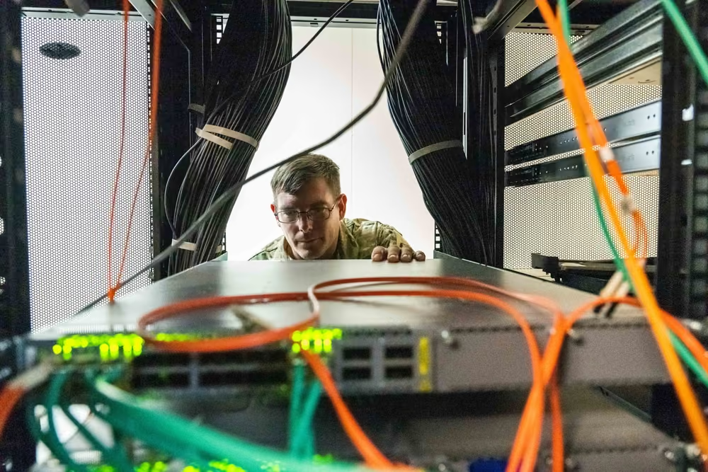
Remote data can identify temperature excursions, link errors, power anomalies, or failed self-tests, yet resolution often requires a person at the machine. The technician must find the correct chassis, verify isolation, inspect connectors and indicators, collect logs, replace the intended unit, and return the node to a known configuration. Ambiguous labels or inaccessible components turn a routine repair into extended downtime.

This documentary image records a real server-inspection context rather than a specific AI fault. It demonstrates the enduring human layer of digital infrastructure: procedures, instruments, access, and judgment. It should not be interpreted as an endorsement, a depiction of the exact products discussed here, or evidence about their reliability. Its relevance is operational—the machine must be designed for diagnosis as well as peak computation.

A technician inspecting cabling and components at the rear of a populated server rack.

A technician inspects server infrastructure, illustrating the human diagnostic work that follows machine telemetry.

Documentary operational context; the equipment is not identified here as an AI accelerator system and no failure rate is inferred.DVIDS marks the item public domain. It documents a server inspection and does not establish the design or performance of an AI cluster. The appearance of U.S. Department of War (DoW) visual information does not imply or constitute DoW endorsement. Individuals' publicity and privacy rights are not waived.DoD photo by David Abizaid, via DVIDS, public domain.Original sourceU.S. government work / public domain
Make telemetry operational evidence
  1. Normalize— Map device-specific sensors, units, severities, identities, and timestamps into a versioned fleet model.
  2. Correlate— Join hardware events with workload, topology, firmware, environmental, and service-history context before assigning cause.
  3. Act— Attach every alert to a tested action such as observe, throttle, drain, reset, repair, or escalate.
  4. Verify— Confirm the action restored the required allocation unit and preserved evidence needed for root-cause review.
Serviceability converts fault data into restored capacity.
02

The rack becomes the computer

Shared fabrics, power shelves, busbars, coolant, and mechanics make the rack a designed system rather than a container of independent servers.

Spread 05 / Tray, chassis, and rack

05 / Physical hierarchy

The enclosure is part of the architecture

Trays, chassis, and rack frames position components while carrying power, coolant, signal, weight, and service loads.

A tray or compute shelf groups modules into a replaceable assembly. Chassis guide airflow or support liquid connections, secure cabling, shield electronics, and establish maintenance access. The rack aligns many assemblies with power shelves, busbars, top-of-rack or internal switching, manifolds, controllers, and structural rails. As integration tightens, these are not generic boxes: hole patterns, depth, load paths, connector placement, and coolant geometry become platform-specific.

Physical packaging influences deployment density and repair. A heavier assembly may require lifts or multiple technicians. Deeper racks affect aisle dimensions and cable reaches. Concentrated loads affect floors and seismic restraints. Blind-mate interfaces can accelerate replacement if alignment and cleanliness are controlled. The rack designer therefore balances compactness against access, standardization against optimization, and maximum density against the facility’s actual power, cooling, and logistics envelope.

Service units
Tray / shelf
A removable compute or infrastructure assembly within a chassis or rack.
Rack
The structural and distribution boundary holding multiple systems and shared services.
Field-replaceable unit
A component designed to be exchanged under documented service procedures.
Rack form factors must be compared at interfaces
InterfaceRecord explicitly
MechanicalRack width, height unit, depth, mass, rails, lifting, and seismic restraint
ElectricalInput, conversion, busbar or cords, redundancy, isolation, and metering
CoolingAir and liquid split, manifolds, flow, pressure, temperatures, and leak controls
NetworkingFront or rear access, cable fields, optics, management, and service clearances
ControlBMC, rack controller, inventory, attestation, firmware, and recovery ownership
Density is useful only when the machine can be installed and repaired.

Rack-scale system

Shared infrastructure couples failures and gains

Rack-level integration can shorten links and simplify distribution while increasing the blast radius of shared components.

When many accelerators share scale-up switches, power conversion, coolant distribution, and management, the rack behaves more like one computer. This can improve communication locality, eliminate repeated components, and expose a coherent operating surface. It also means a failed power shelf, control module, or coolant branch can affect more compute than a fault in an independent server.

Architects use redundancy, isolation, telemetry, and replaceable subassemblies to control that risk. The right boundary depends on maintenance strategy: whether a failed element can be isolated while neighbors run, whether the scheduler can drain affected resources, and whether replacement requires depressurizing or powering down the rack. Rack-scale design should be evaluated by delivered, maintainable capacity—not merely by the count of accelerators installed behind one door.

rack-scale composition documented for NVIDIA DGX GB200
72 GPUs / 36 CPUs
Evidence class
vendor_spec
Claim
claim-gb200-rack-power
Context
One platform specification, not a universal rack architecture or a statement of active utilization.
A rack drawing must survive service
  • Reserve working clearance for technicians, lift devices, drip containment, cable movement, connector inspection, and replacement of the deepest serviceable unit.
  • Model the sequence for isolating power and coolant without taking unrelated trays offline or trapping a partially removed assembly.
  • Check center of gravity, floor loading, shipping splits, anchoring, and the cumulative mass of cables and fluid rather than using chassis weight alone.
  • Label every field-replaceable connection so the physical rack, inventory system, and topology database describe the same object.
A wide illuminated view of the NASA Center for Climate Simulation Discover supercomputer cabinets.

NASA's Discover system makes the machine's cabinet-scale physical boundary visible.

This is scientific HPC infrastructure rather than a current rack-scale AI reference design; cabinet appearance does not disclose internal topology or power density.NASA content is generally not subject to U.S. copyright; agency identification and visible marks are retained for editorial context. This is scientific HPC infrastructure, not a modern NVL72 or an AI rack-density reference.NASA Center for Climate Simulation.Original sourceNASA media usage guidelines
Integration raises both coordination potential and shared-failure stakes.

Spread 06 / Scale-up fabric

06 / Local fabric

Accelerators must exchange state as a system

Scale-up links prioritize high-bandwidth, low-latency communication among accelerators within a tightly coupled domain.

Large models distribute tensors, parameters, activations, or experts across multiple accelerators. During computation, devices exchange partial results and synchronize collective operations. A scale-up fabric provides the local communication plane, using direct links and switches arranged in a defined topology. Its value lies not only in link rate but in path uniformity, collective efficiency, congestion behavior, and how failures partition the machine.

Physical reach is constrained. High-speed electrical channels lose signal quality across connectors and distance, requiring careful materials, routing, and sometimes retiming. More switches increase scale but consume power and add hops. Topology must match how software divides the model: a beautifully connected domain can still underperform if parallel groups cross slower boundaries. Hardware and distributed runtime therefore co-design the logical machine presented to the scheduler.

accelerators in the design scope of UALink 1.0 scale-up fabric
Up to 1,024
Evidence class
fact
Claim
claim-ualink-scale
Context
A specification design target, not evidence that every implementation or workload scales efficiently to this size.
Validate a scale-up domain as one machine
  1. Discover— Verify every endpoint, link, switch, route, firmware revision, and expected topology before allocating work.
  2. Stress— Exercise simultaneous collectives, peer transfers, memory pressure, and compute so shared bottlenecks become visible.
  3. Degrade— Remove or retrain links and peers while observing containment, rerouting, performance loss, and scheduler behavior.
  4. Recover— Prove the domain can return to a known topology without stale routes, hidden errors, or mixed software state.
A scale-up domain is a topology, protocol, and software contract.

Topology / Collectives

Communication patterns consume the links

Broadcast, reduce, gather, and all-to-all operations stress different paths and expose different bottlenecks.

Distributed AI does not generate uniform point-to-point traffic. Data-parallel reductions combine gradients; tensor parallelism exchanges partial activations; pipeline stages pass work in sequence; mixture-of-experts routing can create all-to-all flows. Collective libraries map those patterns onto the available topology, choosing algorithms and chunk sizes that trade latency, bandwidth, and overlap with computation.

A system-level test must represent these patterns rather than rely on isolated link checks. It should observe tail latency, contention, link retraining, error correction, thermal effects, and performance when a path is degraded. Scheduler placement also matters: jobs should receive accelerator groups whose physical connectivity matches the runtime’s assumptions. Otherwise topology fragmentation can strand healthy devices that cannot be assembled into an efficient allocation.

Scale-up evidence
  • Effective bandwidth and latency for representative collectives
  • Topology awareness in runtime and scheduler placement
  • Behavior under a failed or retraining link
  • Contention between simultaneous communication groups
  • Power and thermal behavior during communication-heavy phases
Topology determines the useful failure unit: A healthy accelerator can be unusable when a workload requires the full scale-up domain and one peer or switch path is missing. Availability therefore needs two denominators: device health and allocatable topology. Report collective completion time, tail latency, retries, link imbalance, and behavior under a failed member. A fabric that preserves connectivity but doubles synchronization time may be technically online while economically degraded.
The fabric is productive when collectives—not cables—complete on time.

Spread 07 / Rack power delivery

07 / Conversion chain

Power is converted repeatedly before it computes

Facility voltage becomes rack distribution, shelf output, board rails, and finally the tightly regulated supplies used by silicon.

The rack power path may include switchgear, busway or whips, power shelves, rectifiers, busbars, board-level regulators, package delivery networks, and local decoupling. Each stage provides protection or conversion while introducing loss, heat, control behavior, and a potential fault. Higher density reduces the practicality of repeating small power supplies in every server and increases the value of coordinated rack-level distribution.

Designers must consider steady load, fast transients, startup sequencing, fault current, ride-through, redundancy, metering, and safe isolation. Rated input is not the same as continuous workload draw, yet upstream equipment must accommodate credible operating and transient envelopes. Efficiency also varies with load and temperature. A rigorous model names the measurement boundary—from facility feed to package—and keeps conversion losses separate from useful IT power.

Grid-to-gate path
  1. Distribute— Bring protected facility power to the rack boundary.
  2. Convert— Produce a common rack or shelf-level DC supply.
  3. Regulate— Create board and device voltage rails near the loads.
  4. Stabilize— Manage transients at package and on-die timescales.

The curve is a conservative planning scenario: one rack held continuously at the documented approximate nameplate envelope, without utilization, maintenance, throttling, or conversion adjustments. It is not a consumption forecast. Metered average wall power and operating-state time must replace nameplate for energy, cost, heat, or emissions; tariffs, losses, and facility overhead require separate assumptions.Claim

Cumulative 100%-nameplate rack energy scenario

A derived upper-bound-style scenario using the documented approximate NVL72 rack power continuously through one year.
Cumulative nameplate scenarioGWh
View chart values
Cumulative 100%-nameplate rack energy scenario — underlying values in GWh
CategoryCumulative nameplate scenario
Month 00 GWh
Month 30.26 GWh
Month 60.53 GWh
Month 90.79 GWh
Month 121.05 GWh

DERIVED SCENARIO — assumes continuous 100% of the documented approximate rack envelope; not metered load, forecast, or expected annual energy.

Every conversion stage must be efficient, observable, and safely isolatable.

Density / Planning

A rack specification reaches into the power plant

High rack density changes busways, floor layouts, cooling, redundancy, commissioning, and the number of racks a site can energize.

A high-power rack concentrates demand into a small footprint. The building must deliver current through compatible switchgear, busway, connectors, and conductors while removing roughly the corresponding heat. That can alter row length, electrical rooms, coolant piping, floor loading, and maintenance procedures. A site with abundant total megawatts may still lack the distribution architecture required by a specific rack platform.

Roadmaps toward substantially denser AI racks are planning signals, not proof that such systems are broadly deployed. Facilities and vendors must align standards, connector safety, liquid-cooling interfaces, test equipment, and commissioning methods before density becomes repeatable capacity. The practical question is not the maximum imaginable rack, but which envelopes can be delivered, cooled, maintained, and supported across a fleet without custom engineering at every site.

documented rack power envelope for NVIDIA DGX GB200
≈120 kW
Evidence class
vendor_spec
Claim
claim-gb200-rack-power
Context
Rated platform envelope; actual demand is workload- and configuration-dependent.
Roadmap boundary: Open standards work addressing 250 kW toward 1 MW rack envelopes is a projection and coordination agenda, not a census of operating racks.
Power acceptance is dynamic
  • Measure startup, idle, representative work, communication bursts, throttling, and shutdown at the same facility boundary used for capacity planning.
  • Challenge loss of a feed, shelf, conversion module, controller, or sensor and verify protection selectively contains the fault without unsafe backfeed.
  • Correlate rack telemetry with upstream meters and cooling response so missing loads, conversion losses, and timestamp drift cannot hide in separate systems.
  • Retain headroom criteria for transients and degraded redundancy instead of treating the arithmetic sum of steady ratings as usable capacity.
Rack density is a facility architecture, not a floor-space shortcut.

Spread 08 / Cabling, materials, and mechanics

08 / Physical fabric

Connections consume volume and labor

Copper cables, fiber, power conductors, coolant hoses, management leads, and retention hardware compete for routes and hands.

A rack’s rear plane can be as consequential as its processors. High-speed copper links have limited reach and bend constraints. Optical cables require clean connectors and controlled routing. Power conductors need clearance and strain relief. Coolant hoses must avoid kinks, abrasion, and leak-prone loads. All of them must remain identifiable and accessible after the rack is populated.

Cable management is a reliability discipline. Poor routing can obstruct airflow, stress connectors, complicate service, or turn one replacement into several accidental disconnects. Standard lengths reduce inventory but may create excess slack; optimized lengths reduce clutter but increase part variety. Labeling, color conventions, digital topology records, torque specifications, and inspection procedures help preserve the designed state as technicians work on the machine over time.

Route by constraint
  • Signal reach, bend radius, insertion loss, and connector cleanliness
  • Power clearance, current, heat, strain relief, and touch safety
  • Coolant pressure, bend, abrasion, drip management, and isolation
  • Service access, labeling, tool clearance, and replacement sequence
Manage a cable as a lifecycle asset
  1. Design— Specify media, length, bend, insertion loss, connector, route, airflow, service slack, and compatibility.
  2. Install— Inspect, clean, label, support, route, and test each end while recording the actual physical path.
  3. Operate— Trend errors and environmental exposure without assuming every link fault originates in the transceiver.
  4. Change— Update topology and inventory after replacement, then retest adjacent paths disturbed by the work.
The unglamorous rear plane determines whether the front plane stays available.

Materials / Load path

The rack is a mineral and structural system

Steel and aluminum carry mass; copper carries current and signals; polymers insulate; specialty materials appear throughout electronics and backup systems.

Compute infrastructure depends on a much broader material set than silicon. Frames, rails, fasteners, busbars, printed circuit boards, connectors, magnets, capacitors, batteries, optics, and cooling equipment each draw from different mineral and chemical supply chains. U.S. Geological Survey mapping shows that several minerals used in data-center equipment carry substantial import dependence, making procurement exposure a physical-infrastructure concern.

Material demand should not be inferred from one representative rack ratio because designs vary and supplier bills of materials are often proprietary. A better approach maps function to material class, identifies where substitution is technically plausible, and tracks recycling or recovery at component retirement. Structural engineering also matters immediately: concentrated rack and tray loads must travel through rails, frames, anchorage, raised floors or slabs, and building foundations.

Evidence rule: Mineral dependency is real, but generic kilograms-per-rack extrapolations are not used without a representative, sourced product bill of materials.
Nominally separate routes can share one failure
Shared elementFailure mechanism
Cable trayMaintenance, overload, heat, liquid, or physical damage affects both paths
Patch panelOne panel or labeling error disconnects redundant links together
Rack entryCongestion and bend stress concentrate at the same opening
Power domainBoth active endpoints fail despite diverse physical media
Control planeA common configuration or firmware change removes all paths
A machine is a global materials assembly under local structural loads.
03

Cooling, reliability, and service

Cold plates, manifolds, coolant distribution, telemetry, spares, and procedures convert rated hardware into sustained fleet capacity.

Spread 09 / Heat and sustained performance

09 / Thermal load

Nearly every input watt becomes heat

The machine must move heat away from junctions quickly enough to preserve performance, reliability, and safe operation.

Accelerators, CPUs, memory, switches, voltage regulators, fans, pumps, and power conversion dissipate electrical energy as heat. The thermal path begins inside semiconductor packages, crosses interfaces into heat sinks or cold plates, enters air or liquid, and eventually reaches facility heat-rejection equipment. A bottleneck at any layer raises component temperature even if downstream equipment has unused capacity.

Thermal design must cover spatial and temporal variation. Workloads create hotspots and rapid power changes; neighboring modules may not load evenly; fouling or trapped gas can alter coolant performance; and sensor placement may miss local conditions. Control systems balance temperatures, flow, fan or pump energy, acoustics, and fault response. Sustained compute should be measured under representative thermal equilibrium, not only during a short run before the machine heats fully.

Thermal evidence chain
  1. Sense— Measure junction, package, coolant, air, and ambient conditions.
  2. Transport— Validate interfaces, flow, pressure, and heat-transfer surfaces.
  3. Control— Adjust workload, pumps, fans, and valves within safe limits.
  4. Sustain— Test after temperatures and flows reach steady behavior.
Thermal limits need distinct meanings
Design point
The declared load and environmental condition used to size a cooling path with stated margin and redundancy.
Control point
The temperature, flow, pressure, or power signal that drives fans, pumps, valves, workload placement, or throttling.
Protection point
The boundary that triggers containment or shutdown before hardware, coolant, connectors, or neighboring systems enter unsafe conditions.
Short bursts describe silicon; thermal equilibrium describes the machine.

Derating / Reliability

Temperature converts specifications into operating limits

Devices manage temperature and power through control policies that can change clock rate, voltage, and workload availability.

Modern components monitor internal conditions and may throttle, cap power, retrain links, or shut down to protect hardware. Those behaviors are necessary safety mechanisms, but they mean a nameplate compute figure does not guarantee sustained fleet output. Cooling variation can also create performance variation across nodes, complicating synchronized jobs that wait for the slowest participant.

Operating colder is not automatically optimal. Lower coolant temperatures may increase facility energy or condensation risk, while aggressive flow may raise pump power, erosion, vibration, or pressure. Engineers choose set points that balance component reliability, performance consistency, cooling efficiency, and environmental boundaries. Telemetry should connect thermal conditions to workload throughput and errors so the fleet can distinguish a cooling constraint from a software or silicon constraint.

System metric: The relevant output is sustained, error-free work per unit of facility input—not the highest short-duration component clock.
Instrument the entire heat path
  • Correlate junction or package sensors with cold-plate inlet and outlet temperatures, flow, pressure drop, rack power, and facility-loop conditions.
  • Calibrate sensor offsets and timestamp alignment before diagnosing spatial hot spots or fast transients from data collected by different controllers.
  • Test partial flow, fouling, air ingestion, failed fans, warmer supply, and mixed workloads; a nominal steady-state run does not establish fault margin.
  • Report throttled performance and recovery hysteresis alongside temperature so thermal protection cannot masquerade as stable workload behavior.
Thermal consistency is a distributed-computing feature.

Spread 10 / The rack liquid loop

10 / Direct liquid cooling

Cold plates bring the heat sink to the silicon

A direct-to-chip loop uses cold plates, hoses, manifolds, quick disconnects, and a coolant distribution unit to transport concentrated heat.

Cold plates clamp to high-power packages and transfer heat into a flowing coolant. Flexible or rigid lines connect plates to node and rack manifolds. Quick disconnects make assemblies replaceable while attempting to limit spills and air entry. A coolant distribution unit separates or conditions the technology loop, controls flow and temperature, filters fluid, and exchanges heat with the facility loop.

Every interface carries requirements: allowable pressure, flow, chemistry, particle level, temperature, materials compatibility, leak detection, and service sequence. Too little flow can overheat devices; too much pressure can stress seals or plates. Mixed metals can corrode in an unsuitable fluid. Air pockets can reduce heat transfer. Liquid cooling is therefore not a single component purchase but a controlled fluid system spanning packages, racks, and the plant.

Loop components
Cold plate
Heat exchanger attached directly to a processor or other component.
Manifold
Distribution header dividing coolant among branches.
CDU
Coolant distribution unit controlling and exchanging heat between loops.
Quick disconnect
Serviceable coupling designed to separate fluid lines with limited release.
Cooling architecture is a compatibility decision
ChoiceAdvantageBoundary to qualify
AirSimple dry service pathHeat density, fan power, airflow, and acoustics
Cold plateTargets high-flux componentsContact, flow, pressure, chemistry, and residual air cooling
Rear-door exchangeAdds rack-level heat captureDoor access, weight, airflow, water, and room layout
ImmersionBroad component contactFluid/material compatibility, service, filtration, and containment
The liquid path is both cooling infrastructure and a service interface.

Resilience / Leak response

Design the failure before filling the loop

Isolation valves, drip management, sensors, containment, and procedures determine whether a fluid fault stays local.

Liquid near electronics changes failure planning. Systems use compatible coolants, robust joints, pressure controls, leak detection, and branch isolation to reduce likelihood and impact. Maintenance procedures define how to drain, purge, cap, reconnect, and verify a circuit. Rack layout should keep likely leak paths away from energized components where possible and provide a clear route for inspection.

Resilience also includes loss of flow or heat rejection without a visible leak. Pumps, controls, filters, valves, and heat exchangers need telemetry and sometimes redundancy. The scheduler may need to drain workloads quickly when a thermal branch degrades. Commissioning verifies flow balance, sensor behavior, alarms, and shutdown logic under representative faults. A high-density rack is safe to operate only when thermal protection works as an integrated control system.

Commission the loop
  1. Clean— Flush, filter, and verify material compatibility.
  2. Balance— Set branch flow and validate pressure across loads.
  3. Challenge— Test alarms, isolation, loss-of-flow, and shutdown behavior.
  4. Record— Baseline chemistry, sensors, flow, temperature, and leakage checks.
Prove liquid-fault containment
  1. Detect— Challenge leak, low-flow, high-temperature, pressure, pump, valve, and sensor faults at realistic locations.
  2. Contain— Verify isolation, drip management, electrical protection, workload throttling, and shutdown occur in the intended order.
  3. Restore— Drain or disconnect safely, repair the failed unit, refill, purge air, and confirm chemistry and cleanliness.
  4. Requalify— Repeat pressure, leak, flow, thermal, sensor, and workload checks before returning capacity to the scheduler.
Fault containment is part of cooling capacity.

Spread 11 / Reliability and serviceability

11 / Availability

Installed accelerators are not the same as available accelerators

Faults, updates, diagnostics, topology fragmentation, and repair queues reduce the capacity a scheduler can actually allocate.

A fleet contains machines in different states: healthy and allocatable, reserved, draining, updating, degraded, failed, awaiting parts, or under investigation. An accelerator may pass local diagnostics but remain unusable because its scale-up group is incomplete or its node cannot join the expected network topology. Availability must therefore be measured at the allocation unit required by workloads, not only by individual-device uptime.

Reliability engineering connects error telemetry, work orders, firmware versions, environmental conditions, and lot genealogy. Repeated correctable errors may predict a later failure; an apparent hardware issue may originate in cabling, coolant, or software. Fast replacement helps, but indiscriminate swapping can erase evidence. Mature operations preserve logs and failed parts, classify root causes, and feed lessons back into design, spares, diagnostics, and supplier quality.

Capacity states
Installed
Physically present hardware, regardless of readiness.
Energized
Connected and powered, but not necessarily qualified for jobs.
Allocatable
Healthy capacity the scheduler can assign under current topology rules.
Productive
Allocatable capacity completing useful workload work.
A RAS event needs a controlled state transition
  1. Detect and classify— Preserve counters and workload context, then distinguish corrected, contained, uncontained, transient, and persistent behavior.
  2. Drain and contain— Stop new placement, protect neighboring work, and keep the failed allocation unit available for diagnosis where safe.
  3. Repair or reset— Apply the supported recovery mechanism only after evidence collection and dependency checks are complete.
  4. Validate and release— Run targeted diagnostics plus representative stress, then return the complete required topology or escalate to replacement.
Fleet capacity is a state model, not a purchase count.

Maintenance / Spares

Repair time is designed into the rack

Replaceable units, diagnostics, access, trained labor, firmware controls, and local inventory determine restoration speed.

Serviceability starts with the product architecture. A technician needs a fault that can be isolated, a part that can be reached safely, connectors that tolerate the replacement sequence, and a test that confirms restoration. Liquid-cooled hardware adds draining or dry-disconnect steps. Heavy trays may require lifting equipment. Dense cable fields make documentation and port identity essential.

The service supply chain extends beyond spare accelerator modules. Power shelves, pumps, valves, controllers, optics, cables, fans, seals, filters, and specialized tools can each block recovery. Inventory policy should reflect failure rate, lead time, interchangeability, and the capacity lost while waiting. Firmware and configuration also need rollback-safe spares; a physically compatible unit may not be operationally compatible until its exact software state is controlled.

Mean-time-to-repair ingredients
  • Actionable fault isolation and preserved diagnostic evidence
  • Safe access, lifting, electrical isolation, and fluid procedure
  • Correct local spare, tool, cable, seal, and consumable inventory
  • Technician training plus validated replacement instructions
  • Post-repair test, firmware alignment, and scheduler return-to-service

The documented counts compare two NVIDIA memory-error mechanisms, not failure probabilities. Legacy page retirement removes affected memory regions in software; Ampere-and-later row remapping substitutes hardware spare rows and requires a reset. A larger mechanism capacity does not establish better field reliability, remaining device life, or an automatic RMA threshold. Operators must inspect remap-bank availability, error severity, recurrence, workload impact, and vendor policy.Claim

Documented NVIDIA memory-repair mechanism capacity

Maximum legacy frame-buffer page retirements compared with Ampere-and-later frame-buffer row remappings in NVIDIA guidance.
Documented maximumentries
View chart values
Documented NVIDIA memory-repair mechanism capacity — underlying values in entries
CategoryDocumented maximum
Legacy page retirements64 entries
Ampere+ row remappings512 entries

VENDOR MECHANISM LIMITS — not observed failures, fleet reliability, usable spare rows in a specific device, or an RMA recommendation.

Availability is manufactured again every time a machine is repaired.
04

Deployment and lifecycle

Manufacturing, logistics, installation, acceptance, configuration, refresh, and recovery govern the machine beyond its specification sheet.

Spread 12 / Build, ship, install, accept

12 / Industrialization

A design reaches the fleet through a production system

ODMs and integrators coordinate boards, mechanics, power, cooling, firmware, suppliers, test fixtures, configuration, and quality records.

Machine production draws components from specialized semiconductor, memory, networking, power-electronics, mechanical, and cooling suppliers. Original design manufacturers and system integrators assemble them under product-specific work instructions and test coverage. A qualified design still must survive volume changes, alternate lots, firmware revisions, operator variation, and factory transfers without drifting outside its acceptance envelope.

Configuration control is critical because visually similar racks may contain different component revisions, cable maps, power limits, or coolant requirements. Serial-number genealogy, as-built records, firmware manifests, and factory test results should arrive with the equipment. These records help the site plan installation and later isolate fleet issues. Industrialization is complete only when factories can produce repeatable machines and operators can identify exactly what was delivered.

Factory-to-floor chain
  1. Configure— Lock approved parts, firmware, drawings, and work instructions.
  2. Assemble— Build with traceability and in-process controls.
  3. Test— Exercise power, links, cooling interfaces, and management.
  4. Ship— Protect mass, connectors, fluids, and configuration records.
  5. Accept— Re-verify the installed machine against site interfaces.
Factory-to-site acceptance ladder
  1. Receive— Reconcile serials, configuration, shipping indicators, parts, certificates, and visible mechanical or fluid damage.
  2. Baseline— Capture firmware, identity, attestation, inventory, sensors, topology, power, cooling, and management reachability.
  3. Stress— Run concurrent compute, memory, storage, network, power, and cooling loads at representative environmental conditions.
  4. Challenge— Inject recoverable faults, maintenance actions, reboots, link loss, and degraded redundancy while preserving evidence.
  5. Accept— Compare predeclared limits, archive results, record deviations, and release only complete scheduler allocation units.
As-built evidence travels with the physical machine.

Field plate / Installation

Delivery is an engineered event

Site readiness, rigging, inspection, connection, commissioning, and acceptance convert shipped hardware into energized capacity.

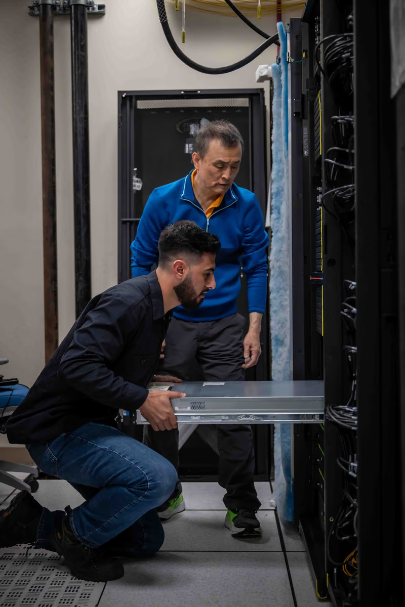
Large compute systems require coordinated arrival. Routes, docks, doors, elevators, floor loading, lifts, staging space, security, and technician schedules must be ready. Teams inspect shipping indicators and physical condition, anchor racks, connect power and grounding, route network links, complete coolant circuits, load approved firmware, and run acceptance tests. One missing adapter, valve, cable, or software entitlement can delay an otherwise complete installation.

The photograph documents real high-performance-computing equipment installation and should be read for its operational context: technicians, racks, handling, and connections. It does not identify every visible component as AI-specific, establish the configuration discussed elsewhere, or demonstrate that the system is commissioned. Installation is a project state between delivery and useful operation; acceptance evidence is what moves the machine onward.

Technicians installing high-performance computing equipment into a tall server rack.

Technicians install documented high-performance-computing infrastructure, showing the labor and coordination between delivery and operation.

Installation context only; the image does not by itself prove commissioning, utilization, or the exact accelerator configuration.DVIDS marks the item public domain. It documents physical HPC installation, not a complete hyperscale AI rack deployment. The appearance of U.S. Department of War (DoW) visual information does not imply or constitute DoW endorsement. Individuals' publicity and privacy rights are not waived.U.S. Navy photo by Travis Troller, via DVIDS, public domain.Original sourceU.S. government work / public domain
Acceptance evidence should be replayable
ArtifactRequired content
Configuration manifestHardware, firmware, software, topology, and security state
Test definitionWorkload, duration, environment, limits, instrumentation, and expected faults
Raw result bundleCounters, logs, timestamps, power, thermal, network, and storage traces
Exception ledgerFailure, disposition, repair, retest, approver, and residual restriction
Release recordAccepted allocation unit, date, baseline, owner, and rollback path
Delivered, installed, energized, accepted, and productive are separate states.

Spread 13 / Refresh, reuse, and retirement

13 / Fleet lifecycle

The machine changes after launch

Firmware, models, failures, parts availability, energy cost, and new hardware alter the value of installed systems over time.

A compute fleet is not static inventory. Software updates may unlock performance or require new compatibility testing. Component aging and repeated service create mixed hardware populations. New accelerator generations can deliver different memory, power, network, and cooling requirements, complicating whether an existing rack or hall can accept a partial refresh. Operators balance utilization, reliability, support status, energy efficiency, and migration risk.

Refresh planning should separate technical obsolescence from lack of demand. Older machines may remain useful for inference, development, evaluation, or workloads with different precision and latency needs. Redeployment can extend productive life if security, support, data governance, and operating cost remain acceptable. A platform that is modular, well-instrumented, and documented preserves more options than one whose useful parts cannot be isolated or supported.

Possible end-of-first-use paths
PathDecision testDependency
ContinueStill reliable and economicalParts and software support
RedeployUseful for another workload or siteSecurity, compatibility, transport
HarvestComponents retain service valueTraceability and safe testing
RecycleMaterial recovery is the best remaining routeCertified handling and downstream chain
Cost follows productive time, not purchase quantity
TCO componentMeasurement boundary
CapitalDelivered system, integration, facility adaptation, financing, and depreciation period
EnergyMetered wall power by state, hours, tariff, losses, and facility overhead
OperationsSoftware, support, labor, spares, consumables, testing, and planned maintenance
UnavailabilityQueue delay, failed work, repair time, fragmented topology, and reserved headroom
RetirementData removal, de-installation, resale, recycling, waste, and facility restoration
Modularity preserves choices after the first workload changes.

Synthesis / Machine

Design the exit before the rack arrives

Asset records, data sanitization, repairability, material disclosure, resale controls, and recycler qualification determine the final handoff.

Electronics retirement carries security and environmental obligations. Storage and controller devices may retain sensitive data or credentials. Batteries, coolants, capacitors, and other components require appropriate handling. Valuable metals and working modules can be recovered only when equipment is identifiable, separable, and routed to accountable downstream processors. Global e-waste totals show why lifecycle design cannot be deferred until decommissioning.

The machine volume ends where the fabric begins. A rack becomes productive only when its scale-up domains connect to scale-out networks, storage systems, schedulers, collectives, runtimes, and observability. Those layers determine which healthy machines can work together and whether installed capacity is actually fed. Physical lifecycle and software lifecycle remain linked: a machine’s useful life depends as much on compatible code and network roles as on whether its fans or pumps still turn.

projected global e-waste generation in 2030
82 million tonnes
Evidence class
projection
Claim
claim-ewaste-2030
Context
Economy-wide electronic waste, not a data-center-only estimate; included to bound the wider lifecycle system.
Dependency handoff: The next volume follows the fabric that turns many serviceable machines into one scheduled, data-fed computing system.
Lifecycle decisions that preserve option value
  • Track component age, duty, repair, firmware, error history, and compatibility so redeployment decisions use condition rather than calendar age alone.
  • Size spares by failure mode, lead time, interchangeability, lost allocation capacity, and diagnostic uncertainty instead of one undifferentiated percentage.
  • Plan secure data removal, fluid handling, batteries, heavy lifts, packaging, resale documentation, and material recovery before the first rack is installed.
  • Compare continued operation, redeployment, harvesting, resale, and retirement using measured efficiency and supportability under the next workload—not original specifications.
A machine’s final design requirement is a responsible next state.

Behind the claim

Evidence, in context.

Opening the evidence record…